An electrical shaft in architecture is a vertical space or conduit designed to house electrical wiring, cables, and related utilities within a building. These shafts provide a safe and organized pathway for electrical systems, ensuring efficient distribution of power, data, and communication lines across multiple floors.
Typically enclosed within walls or dedicated service cores, electrical shafts help in maintaining the building’s aesthetics while protecting wiring from external damage, fire hazards, and unauthorized access. They are strategically placed to minimize energy loss, facilitate maintenance, and comply with building codes and safety regulations.
In high-rise buildings, electrical shafts often integrate with mechanical and plumbing shafts to optimize space and infrastructure planning.
If you want to know about the sump detail one or miscellaneous detail or water tank detail, please click the link.
Image of Electrical shaft detail and downloadable (in DWG) link below
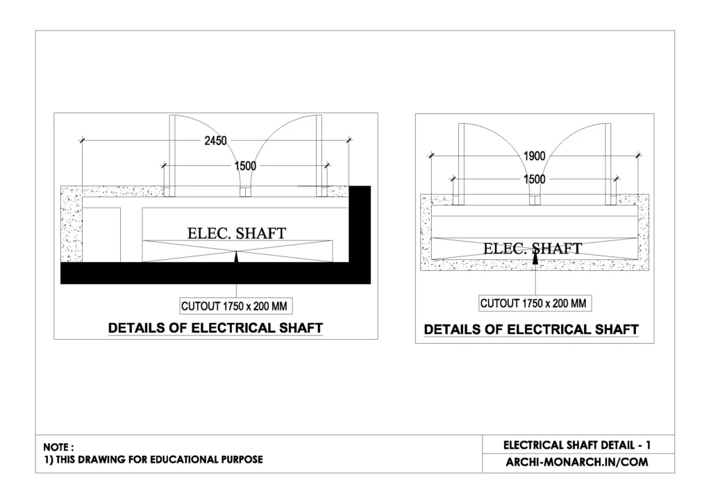
Electrical shaft detail drawing – 1
An electrical shaft detail drawing in construction typically includes the following elements:
- Plan and Section Views – Showing the shaft’s position within the building, dimensions, and relation to other structural elements.
- Materials and Enclosure – Indicating fire-rated walls, access doors, and ventilation if required.
- Cable Trays and Conduits – Depicting the arrangement of electrical conduits, cable trays, and raceways.
- Access Panels and Maintenance Routes – Showing service access points for inspection and repairs.
- Fire Stopping and Safety Features – Highlighting fire barriers, dampers, and sealing methods to prevent fire spread.
- Integration with Other Services – Indicating proximity to plumbing, HVAC, and mechanical shafts.
Our tips to help you improve your architectural Electrical shaft detailing.