


Description
The Walls Along Structural Glazing detail provides a professionally prepared architectural interior standard drawing set in DWG format for educational and reference purposes. Structural glazing systems are widely used in modern architecture to create transparent, lightweight, and visually open spaces. When walls meet or run along structural glazing, designers must carefully coordinate materials, connections, and finishes to ensure stability, weather resistance, and aesthetic continuity. Therefore, architecture students and drafting professionals must understand these interface details to achieve high-performance and well-integrated building interiors.
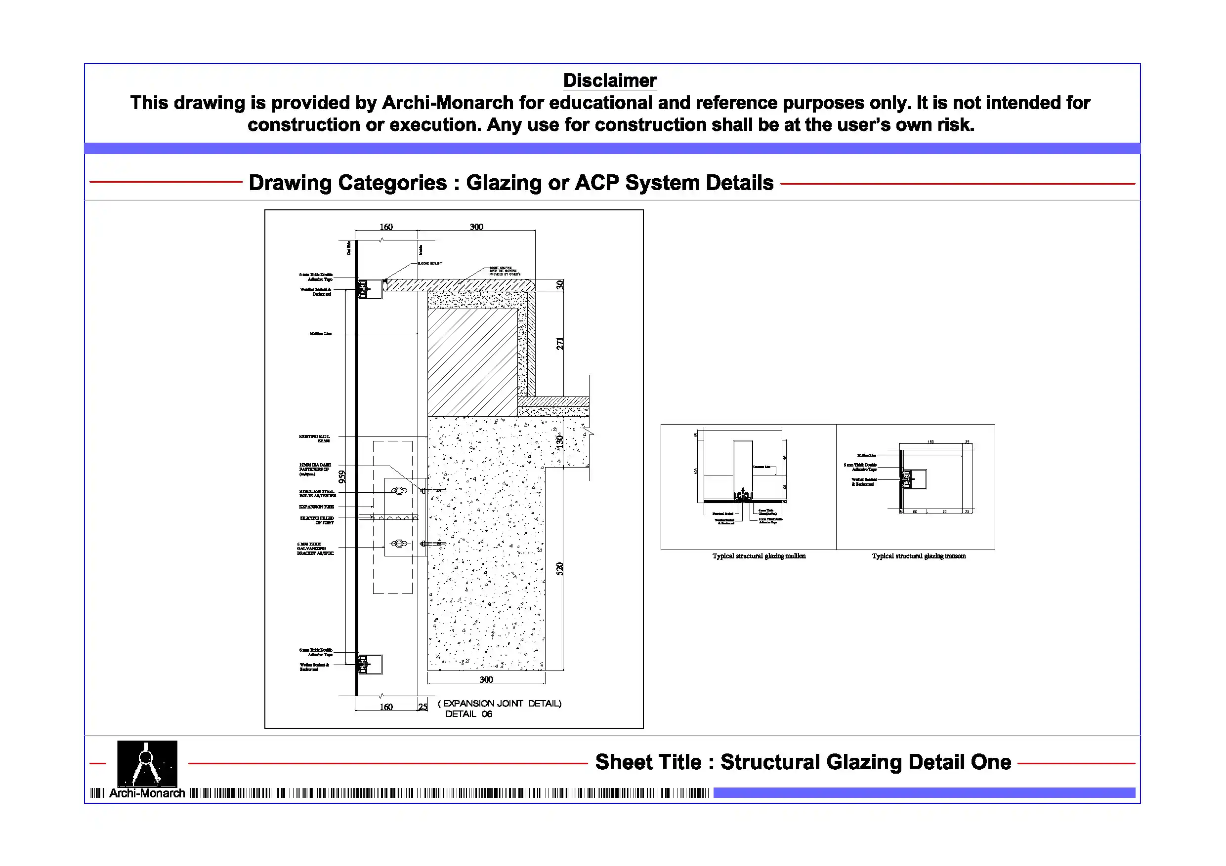
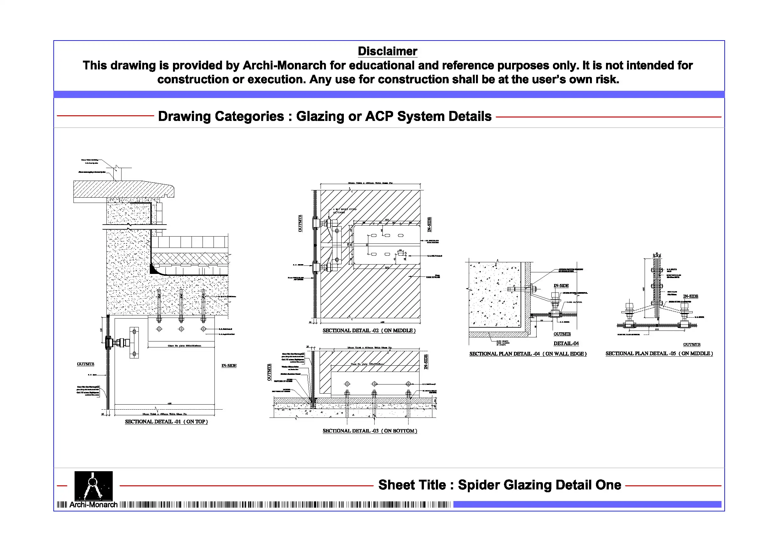
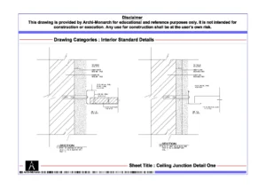
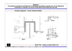
This architectural CAD package clearly presents wall integration with structural glazing through detailed drawings. It includes sectional details, elevations, and construction-specific information in a structured and coordinated format. The drawing set explains how walls align with glazing systems, including junctions between glass panels, framing members, and adjacent wall constructions. It also highlights key components such as structural glass panels, aluminum or steel framing systems, sealants, gaskets, insulation layers, and fixing methods. In addition, it covers finishing treatments, edge detailing, and joint sealing techniques that ensure durability, air-tightness, and water resistance. As a result, users gain practical insight into designing wall-glazing interfaces that improve performance, safety, and visual clarity.
Moreover, the drawings follow professional architectural and interior drafting standards. They use accurate dimensions, clear line hierarchy, and well-organized annotations. Consequently, students can easily interpret the drawings and apply similar detailing techniques in academic projects and CAD exercises. Users can edit the files freely to modify junction conditions, adjust material specifications, or refine detailing to explore different construction solutions.
The DWG format ensures seamless compatibility with AutoCAD and other commonly used CAD software. Therefore, users can directly integrate these drawings into project workflows, presentations, and documentation sets without additional conversion. In addition, the drawing set supports coordination between façade systems, interior walls, and service integration, which improves drafting clarity and technical accuracy.
Key Highlights:
- Walls along structural glazing detail in DWG format
- Intended strictly for educational and reference use
- Includes sectional and construction details
- Shows wall-to-glazing junctions and interface conditions
- Covers glass panels, framing systems, sealants, and fixing methods
- Prepared using professional architectural and interior drafting standards
- Fully editable and AutoCAD-compatible CAD files
- Suitable for architecture students and drafting learners
This drawing set does not serve as a construction-ready document. Always consult qualified architects and façade consultants before applying any detail in real projects.


Reviews
There are no reviews yet.