

Description
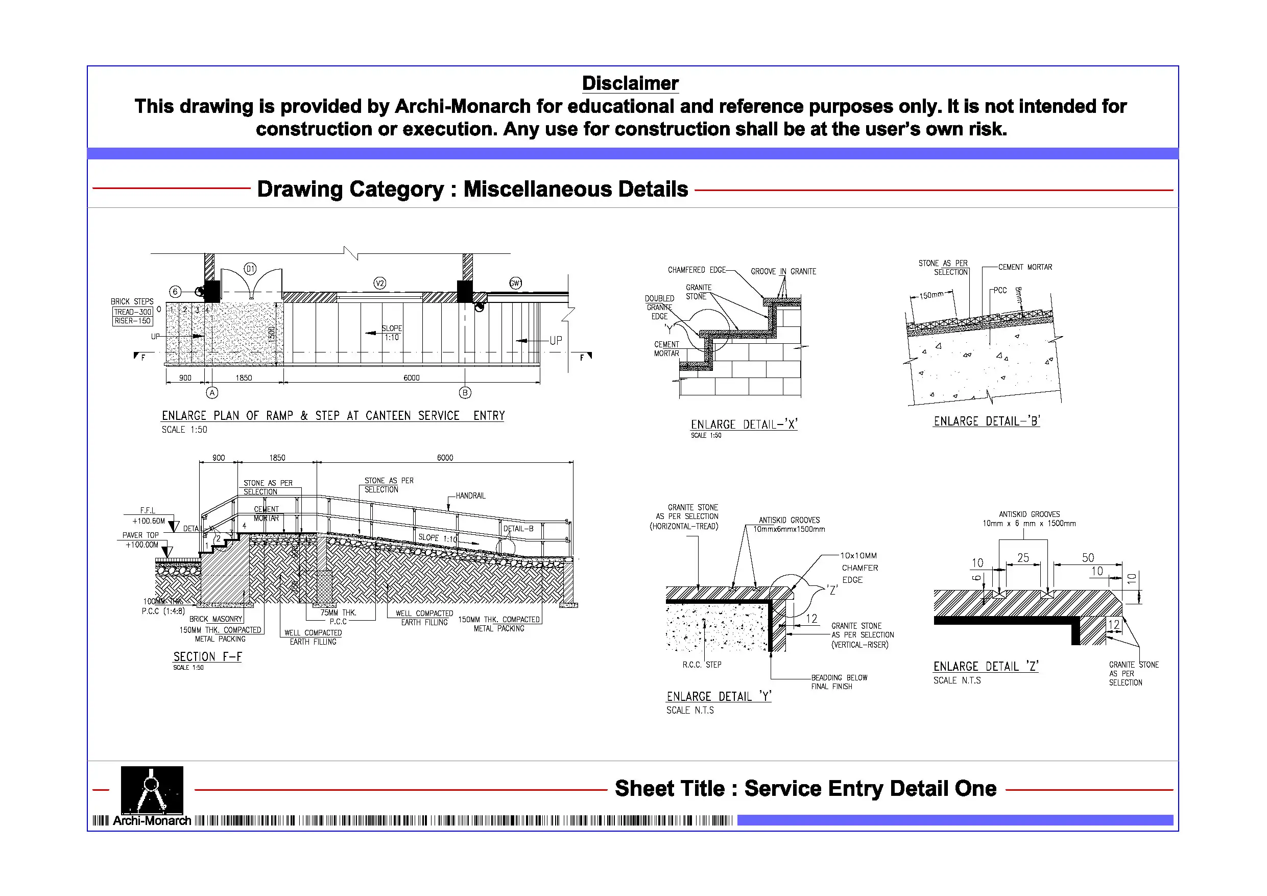
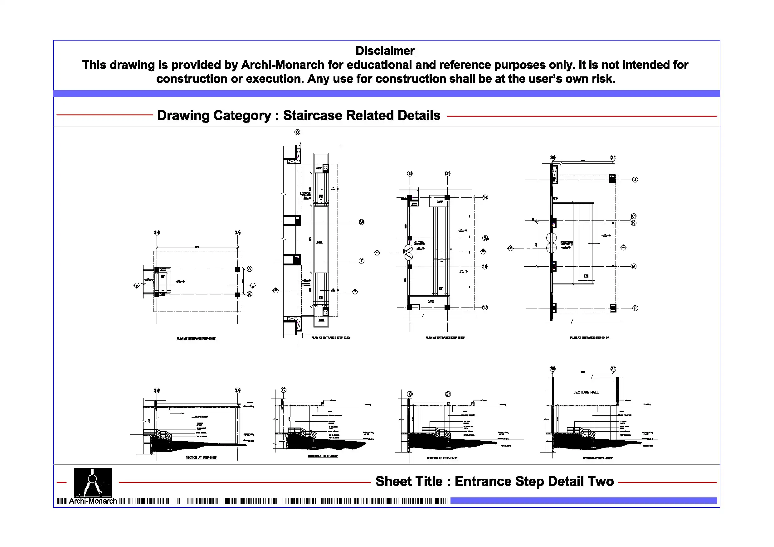
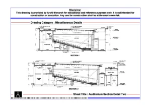
The Service Entry Detail is a professionally prepared architectural miscellaneous drawing in DWG format. It serves educational and reference purposes. Service entry points are essential for routing utilities such as electrical lines, plumbing, HVAC ducts, and maintenance access into buildings. Therefore, proper planning ensures safe, organized, and efficient service distribution. As a result, well-designed service entries improve functionality, accessibility, and building performance.
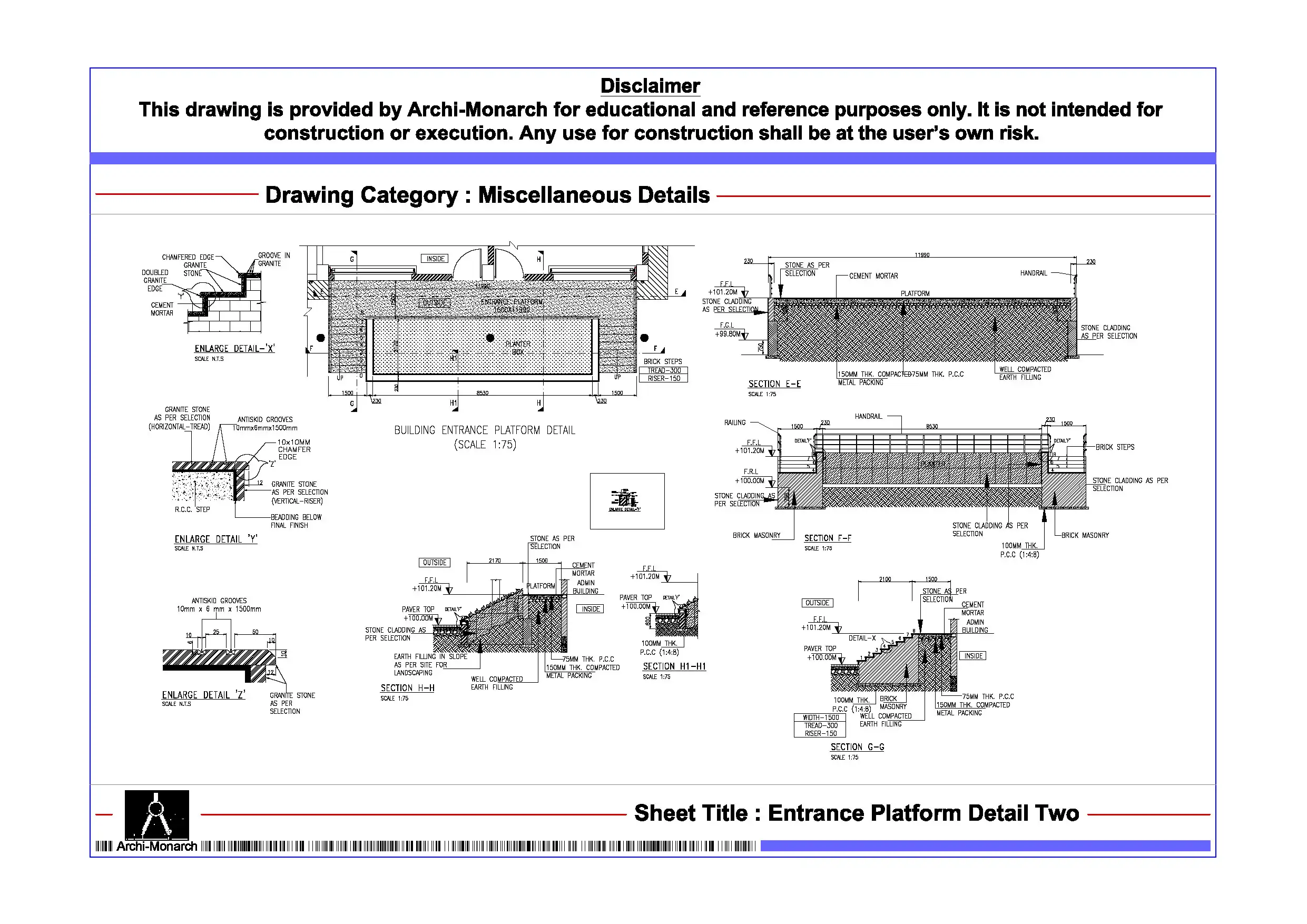
This DWG file provides a detailed service entry system layout. In addition, it suits residential complexes, commercial buildings, hospitals, industrial facilities, and institutional projects. The drawing includes service corridors, entry shafts, cable ducts, pipe sleeves, access doors, trench routing, and structural openings. Furthermore, it allows users to study installation methods and coordination between architectural and MEP systems. Moreover, it helps define performance aspects such as accessibility, safety, maintenance efficiency, and service segregation. Consequently, users can design well-organized and efficient service entry systems.
Moreover, the drawing follows professional architectural and MEP coordination standards. It maintains proper scale, clear annotations, and organized layers. As a result, it ensures clarity and smooth workflow. Therefore, students can easily understand service entry design principles and utility integration concepts. Similarly, professionals can use it as a reference for working drawings and execution details. The file remains fully editable, so users can customize it as required. In addition, they can adapt it to suit different building types, utility loads, and site conditions.
The DWG format ensures compatibility with AutoCAD and similar drafting software. Thus, users can open, edit, and integrate the drawing easily. This also helps save time during design development. Furthermore, it supports coordination with architectural, structural, and MEP drawings.
This service entry detail suits various project types. For example, designers use it in residential buildings, commercial complexes, hospitals, industrial plants, and institutional campuses. Overall, it supports both academic learning and professional workflows.
Key Highlights:
- Service entry detail drawing in DWG format
- Intended for educational and reference use only
- Includes utility entry points, shafts, and routing details
- Suitable for MEP coordination and building services
- Helps define safety, accessibility, and efficiency
- Fully editable and easy to customize
- Compatible with AutoCAD and similar software
- Suitable for students and professionals
This drawing is not a construction-ready document. Therefore, always consult qualified professionals before using it in real projects.


Reviews
There are no reviews yet.