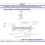
SECTION FOR PAVER BLOCK ONE

Paver blocks are widely used in architecture for outdoor applications such as pathways, driveways, and patios. They are made from concrete or natural stone and come in various shapes, sizes, colors, and patterns. Paver blocks require proper base preparation and can be installed using sand-set, mortar-set, or pedestal-set methods.

Architects have the flexibility to create unique patterns and designs. Paver blocks are low maintenance and can be easily repaired or replaced if damaged. Overall, they offer versatility, durability, and aesthetic appeal to outdoor spaces.

If you want to know about the working drawing or water tank detail or landscape detail, please click the link.

Image of section for paver block detail and downloadable (in DWG) link below

SECTION FOR PAVER BLOCK ONE

Section for paver block detail drawing – 1

In construction, detailed drawings are essential for accurately conveying the design and specifications of paver block installations. These drawings provide crucial information to contractors, engineers, and workers involved in the construction process. Here’s a section discussing the key elements to include in a paver block detail drawing:

  • Plan View: The plan view provides an overhead representation of the paver block installation. It includes the layout, dimensions, and location of the pavers within the designated area. The drawing should clearly show the pattern design, any border details, and transitions to adjacent surfaces.
  • Sectional Views: Sectional views illustrate the vertical dimension of the paver block installation. This includes the layers and materials used in the construction. The drawing should depict the base and sub-base layers, such as compacted soil, crushed stone or gravel, and any required geotextile or drainage systems.
  • Base Preparation Details: The drawing should specify the required excavation depth, compaction requirements, and the thickness of each layer. It should indicate the materials used for the base and sub-base layers and their respective thicknesses. Details such as slope, gradients, and any necessary edge restraints should also be included.
  • Paver Block Specifications: The detail drawing should provide specifications for the paver blocks, including the type, size, and material. It should specify the joint width between the pavers and indicate the recommended jointing material, such as polymeric sand or mortar. If applicable, the drawing should note any special features or variations in paver size or color.
  • Edge Restraints and Transitions: The drawing should clearly show the type and design of edge restraints, such as concrete curbs, metal or plastic edging, or soldier course pavers. It should also illustrate any transitions to existing surfaces or neighboring elements, ensuring a smooth and seamless integration.
  • Drainage and Slope Details: If the paver block installation requires drainage, the drawing should include details on the location and type of drainage systems, such as catch basins, channel drains, or permeable paver systems. The slope or gradient of the surface should also be indicated, ensuring proper water runoff.
  • Construction Notes and Specifications: Construction notes and specifications provide additional information about the installation process, materials, and any special considerations. These notes should be clear, concise, and include any specific instructions or requirements for the paver block installation.

By including these key elements in a paver block detail drawing, architects and designers can effectively communicate the design intent, construction requirements, and specifications to the construction team, ensuring a successful and accurate implementation of the project.


Our tips to help you improve your architectural section for paver block detailing.


Purchase (Section for paver block detail) link below for download

error: Content is protected !!