

Description
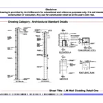
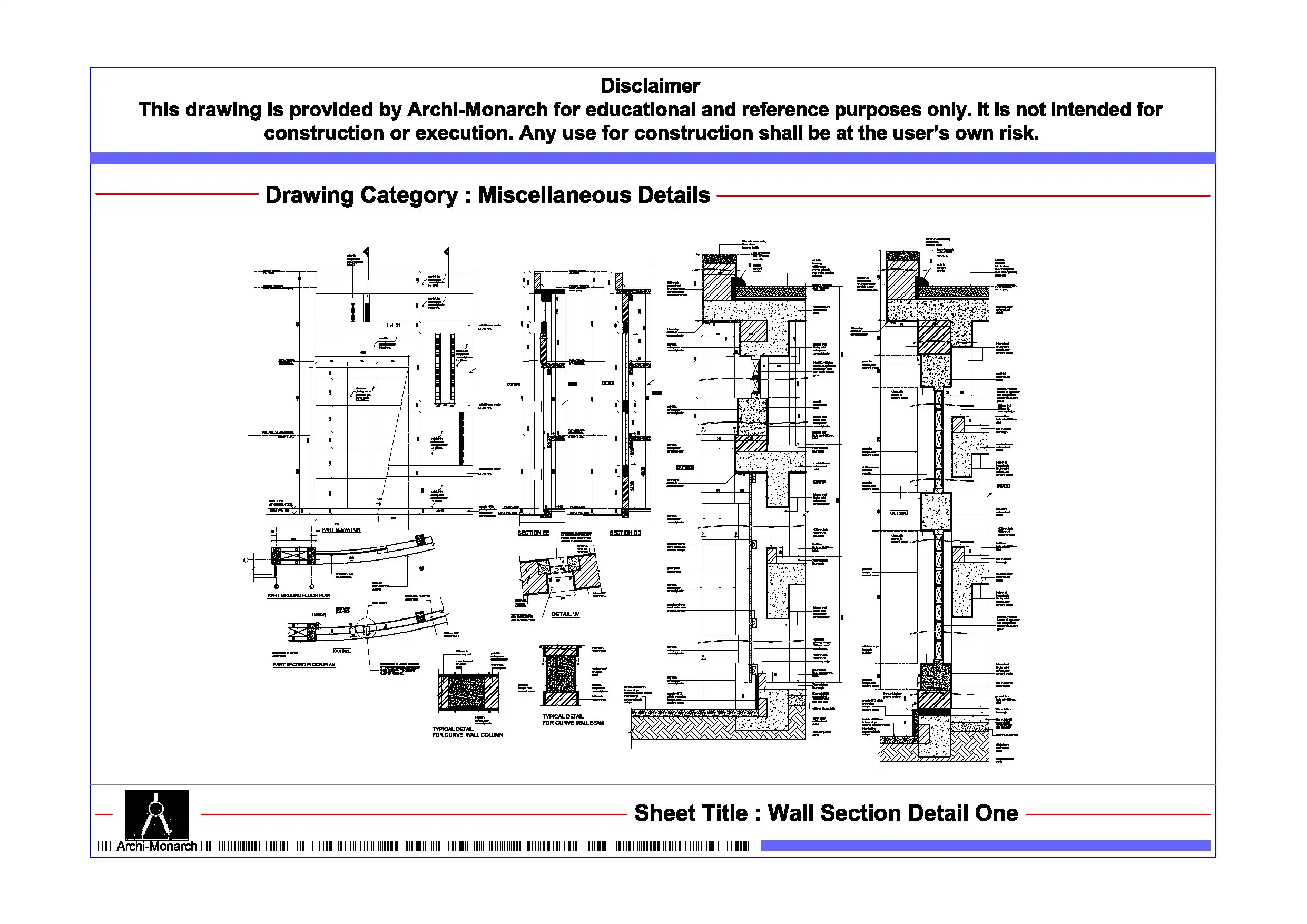
The Lift Wall Cladding Detail provides a professionally prepared architectural standard drawing set in DWG format for educational and reference purposes. Lift lobbies and elevator surrounds are key interior spaces that require durable, visually appealing, and well-coordinated finishes. Designers must carefully plan wall cladding systems to ensure proper fixing, alignment, and integration with lift door frames and structural walls. Therefore, architecture students and drafting professionals must understand lift wall cladding detailing to design high-quality interior finishes that enhance both functionality and aesthetics.
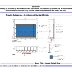
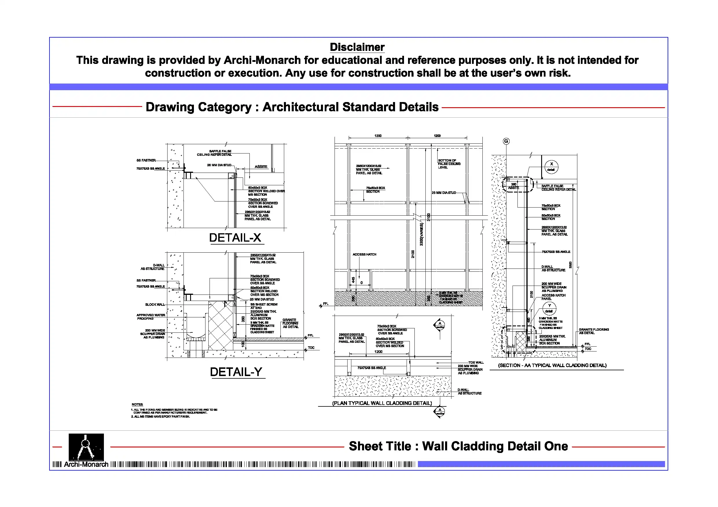
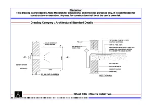
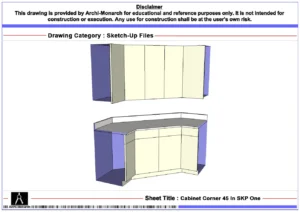
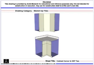
This architectural CAD package clearly presents lift wall cladding design through detailed drawings. It includes sectional details, elevations, and construction-specific information in a structured and coordinated format. The drawing set explains cladding layout, panel dimensions, and integration with lift openings. It also highlights key components such as cladding panels (stone, laminate, metal, or composite), backing framework, support brackets, and fixing systems. In addition, it covers joint detailing, edge trims, alignment with lift door frames, and finishing techniques that ensure precision and durability. The drawings also address material transitions, service coordination, and maintenance accessibility. As a result, users gain practical insight into designing lift wall cladding systems that improve durability, visual quality, and long-term performance.
Moreover, the drawings follow professional architectural and drafting standards. They use accurate dimensions, clear line hierarchy, and well-organized annotations. Consequently, students can easily interpret the drawings and apply similar detailing techniques in academic projects and CAD exercises. Users can edit the files freely to modify panel sizes, adjust materials, or refine detailing to explore different design options.
The DWG format ensures seamless compatibility with AutoCAD and other commonly used CAD software. Therefore, users can directly integrate these drawings into project workflows, presentations, and documentation sets without additional conversion. In addition, the drawing set supports coordination between interior finishes, lift systems, and structural elements, which improves drafting clarity and technical accuracy.
Key Highlights:
- Lift wall cladding detail drawing in DWG format
- Intended strictly for educational and reference use
- Includes sectional and elevation details
- Shows cladding panels, fixing systems, and lift door integration
- Covers joints, edge trims, materials, and finishing techniques
- Prepared using professional architectural and drafting standards
- Fully editable and AutoCAD-compatible CAD files
- Suitable for architecture students and drafting learners
This drawing set does not serve as a construction-ready document. Always consult qualified architects and interior specialists before applying any detail in real projects.


Reviews
There are no reviews yet.