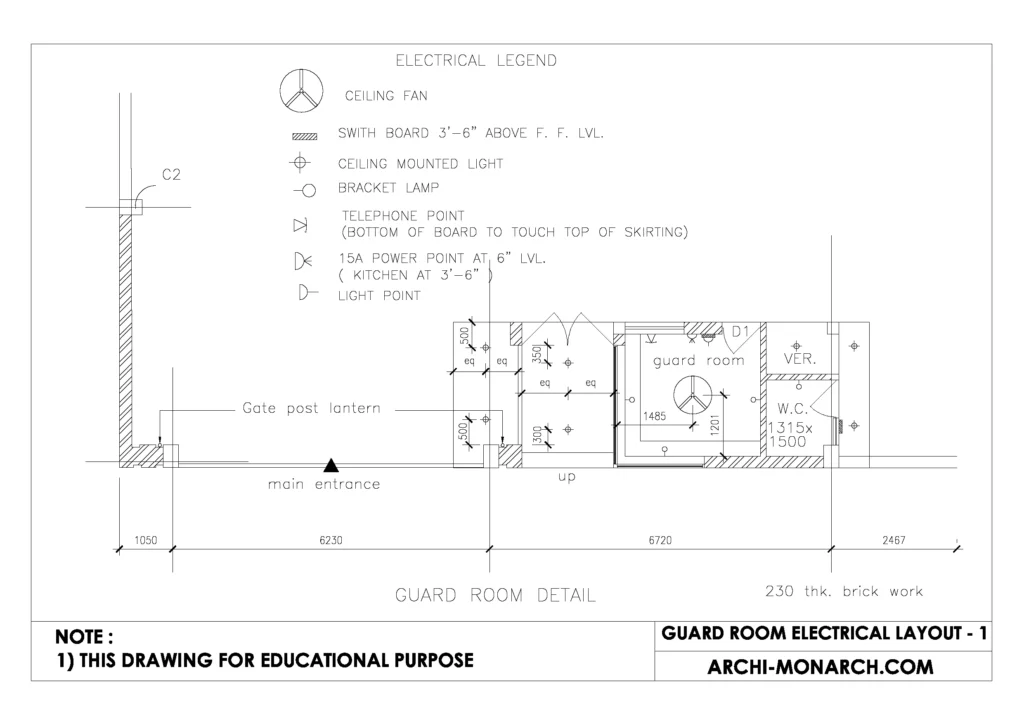
A guard room electrical layout is a diagram or plan that shows the location and arrangement of electrical components and systems within a guard room.
This can include things such as electrical outlets, lighting fixtures, security cameras, and other equipment. The layout should be designed to ensure proper power and data distribution, as well as compliance with local electrical codes and regulations.
The layout should also take into account the specific needs of the guard room, such as providing adequate lighting for security personnel to work effectively.
If you want to know about the staircase detail or toilet detail or ramp detail, please click the link.
Image of Guard rooms electrical layout and downloadable (in DWG) link below

Guard room electrical layout detail drawing – 1
A guard room electrical layout detail drawing is a detailed diagram or plan that shows the specific placement and connections of electrical components and systems within a guard room.
This type of drawing typically includes information such as the location of electrical outlets, light fixtures, security cameras, and other equipment, as well as the type and size of electrical wiring and conduit used. It may also include details such as the types of switches, circuit breakers, and other electrical components used.
A guard room electrical layout detail drawing is an important tool for ensuring that the electrical systems in a guard room are properly installed, connected and comply with the building codes and regulations.
It helps the electricians, engineers and contractors to understand the requirements and to carry out the installation and maintenance of the electrical systems.
A guard room electrical layout detail drawing should also include information on the power distribution system, including the location of main service panels and subpanels, as well as the amperage and voltage of the electrical service. It is important to have the location of emergency lighting, emergency power panels and other safety systems, such as fire alarm and emergency communication systems, clearly indicated on the drawing.
In addition, the drawing should show the location of all data and communication outlets, including telephone and internet connections.
It is also important to have the layout detail drawing to be in compliance with the local and national electrical codes, such as the National Electric Code (NEC), and any other relevant regulations. This will ensure that the electrical systems in the guard room are safe and up to code.
Furthermore, the drawing should be clear and easy to read, with all information presented in a logical and consistent manner. The use of standardized symbols and notations will help to make the drawing easy to understand for all parties involved, including electricians, engineers, and building inspectors.
Overall, a guard room electrical layout detail drawing is a critical tool for ensuring the proper installation and maintenance of electrical systems in a guard room, while also ensuring compliance with codes and regulations.
Our tips to help you improve your architectural guard room electrical layout detailing.
