
Description
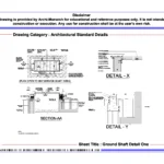
The Ground Shaft Detail provides a professionally prepared architectural standard drawing set in DWG format for educational and reference purposes. Ground-level shafts are critical components in building services, commonly used for ventilation, plumbing access, drainage connections, and service routing. Designers must carefully plan ground shaft construction to ensure proper water management, structural stability, and safe access for maintenance. Therefore, architecture students and drafting professionals must understand ground shaft detailing to design efficient and well-coordinated service systems.
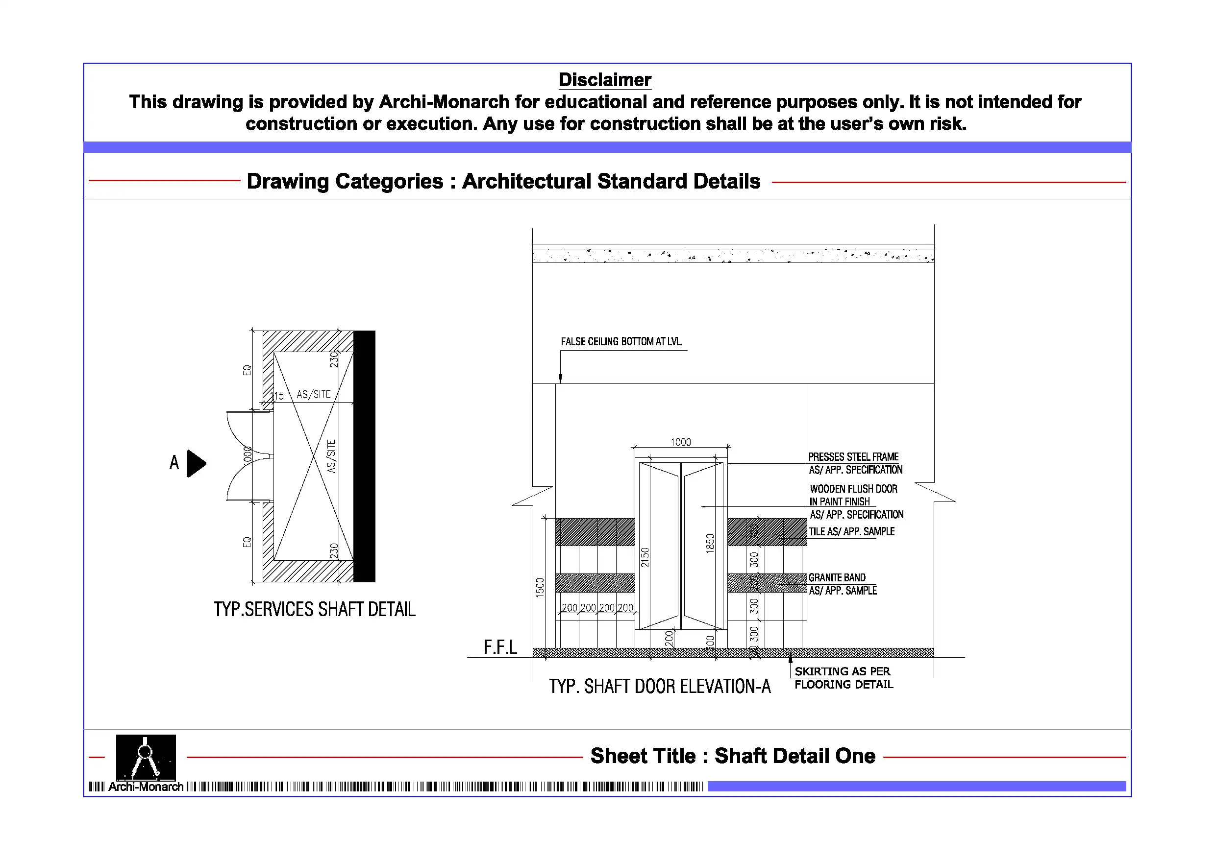
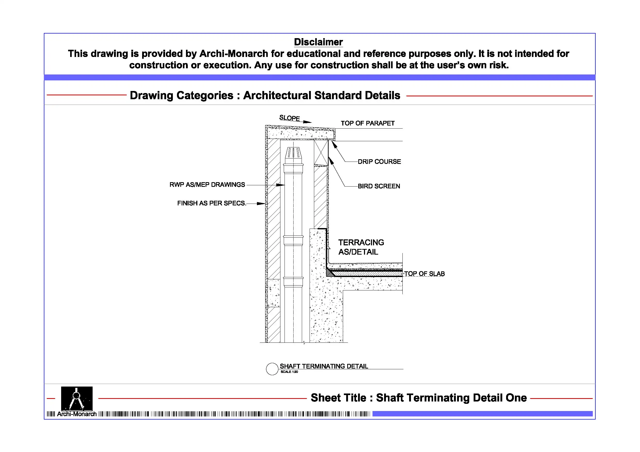
This architectural CAD package clearly presents ground shaft design through detailed drawings. It includes sectional details, plan layouts, and construction-specific information in a structured and coordinated format. The drawing set explains shaft dimensions, depth, and integration with surrounding ground levels and structural elements. It also highlights key components such as shaft walls, base slabs, drainage outlets, grating covers, and access openings. In addition, it covers waterproofing layers, slope formation, joint sealing, and finishing techniques that prevent water accumulation and ensure durability. The drawings also address ventilation provisions and safety measures required for proper shaft functionality. As a result, users gain practical insight into designing ground shaft systems that enhance service efficiency, drainage performance, and long-term reliability.
Moreover, the drawings follow professional architectural and drafting standards. They use accurate dimensions, clear line hierarchy, and well-organized annotations. Consequently, students can easily interpret the drawings and apply similar detailing techniques in academic projects and CAD exercises. Users can edit the files freely to modify shaft dimensions, adjust drainage layouts, or refine detailing to suit different project requirements.
The DWG format ensures seamless compatibility with AutoCAD and other commonly used CAD software. Therefore, users can directly integrate these drawings into project workflows, presentations, and documentation sets without additional conversion. In addition, the drawing set supports coordination between architectural layouts, structural elements, and service systems, which improves drafting clarity and technical accuracy.
Key Highlights:
- Ground shaft detail drawing in DWG format
- Intended strictly for educational and reference use
- Includes sectional and plan details
- Shows shaft construction, drainage integration, and access provisions
- Covers waterproofing, slopes, joints, and finishing techniques
- Prepared using professional architectural and drafting standards
- Fully editable and AutoCAD-compatible CAD files
- Suitable for architecture students and drafting learners
This drawing set does not serve as a construction-ready document. Always consult qualified architects and engineers before applying any detail in real projects.


Reviews
There are no reviews yet.