


Description
The Grease Trap Detail provides a professionally prepared architectural plumbing drawing set in DWG format for educational and reference purposes. Grease traps are essential components in plumbing systems, especially in commercial kitchens, restaurants, and food preparation areas. They are designed to intercept fats, oils, and grease (FOG) from wastewater before it enters the drainage system, thereby preventing blockages and maintaining efficient flow.
Designers must carefully plan grease trap installation to ensure proper separation, accessibility, and long-term performance. Therefore, architecture students and drafting professionals must understand grease trap detailing to design effective and compliant drainage systems.
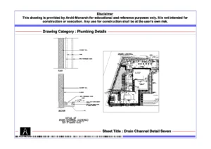
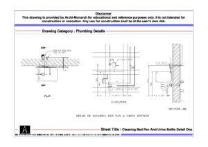
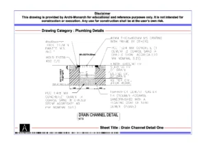
This architectural CAD package clearly presents grease trap construction through detailed drawings. It includes sectional details, plan layouts, and construction-specific information in a structured and coordinated format. The drawing set explains trap dimensions, chamber layout, and positioning within service areas such as kitchens and utility zones. It also highlights key components such as inlet and outlet pipes, baffle walls, grease separation chambers, and cover slabs.
In addition, it covers flow direction, retention time, and sediment collection features that enhance grease separation efficiency. The drawings also address maintenance access, cleaning provisions, and ventilation requirements, ensuring that the system remains functional and hygienic. As a result, users gain practical insight into designing grease trap systems that reduce drainage issues, improve system efficiency, and support sanitary operations.
Moreover, the drawings follow professional architectural and drafting standards. They use accurate dimensions, clear line hierarchy, and well-organized annotations. Consequently, students can easily interpret the drawings and apply similar detailing techniques in academic projects and CAD exercises. Users can edit the files freely to modify trap sizes, adjust pipe connections, or refine detailing to suit different project scales and kitchen requirements.
The DWG format ensures seamless compatibility with AutoCAD and other commonly used CAD software. Therefore, users can directly integrate these drawings into project workflows, presentations, and documentation sets without additional conversion. In addition, the drawing set supports coordination between plumbing systems, kitchen layouts, and civil works, which improves drafting clarity and technical accuracy.
Key Highlights:
- Grease trap detail drawing in DWG format
- Intended strictly for educational and reference use
- Includes sectional and plan details
- Shows grease separation chambers, baffles, and pipe connections
- Covers flow control, maintenance access, and cleaning provisions
- Prepared using professional architectural and drafting standards
- Fully editable and AutoCAD-compatible CAD files
- Suitable for architecture students and drafting learners
This drawing set does not serve as a construction-ready document. Always consult qualified plumbing engineers and follow local sanitation guidelines before applying any detail in real projects.


Reviews
There are no reviews yet.