

Description
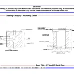
The GT and IC Detail provides a professionally prepared architectural plumbing drawing set in DWG format for educational and reference use. Grease traps (GT) and inspection chambers (IC) are essential components in building drainage systems. They are especially important in areas that handle wastewater containing grease and solid waste.
The grease trap separates fats, oils, and grease (FOG), while the inspection chamber allows access for monitoring, cleaning, and maintenance of pipelines. Designers must plan GT and IC systems carefully to ensure smooth wastewater flow and easy maintenance. This also supports long-term system performance.
Architecture students and drafting professionals should understand GT and IC detailing. This knowledge helps them design efficient and compliant drainage systems.
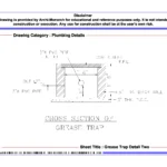
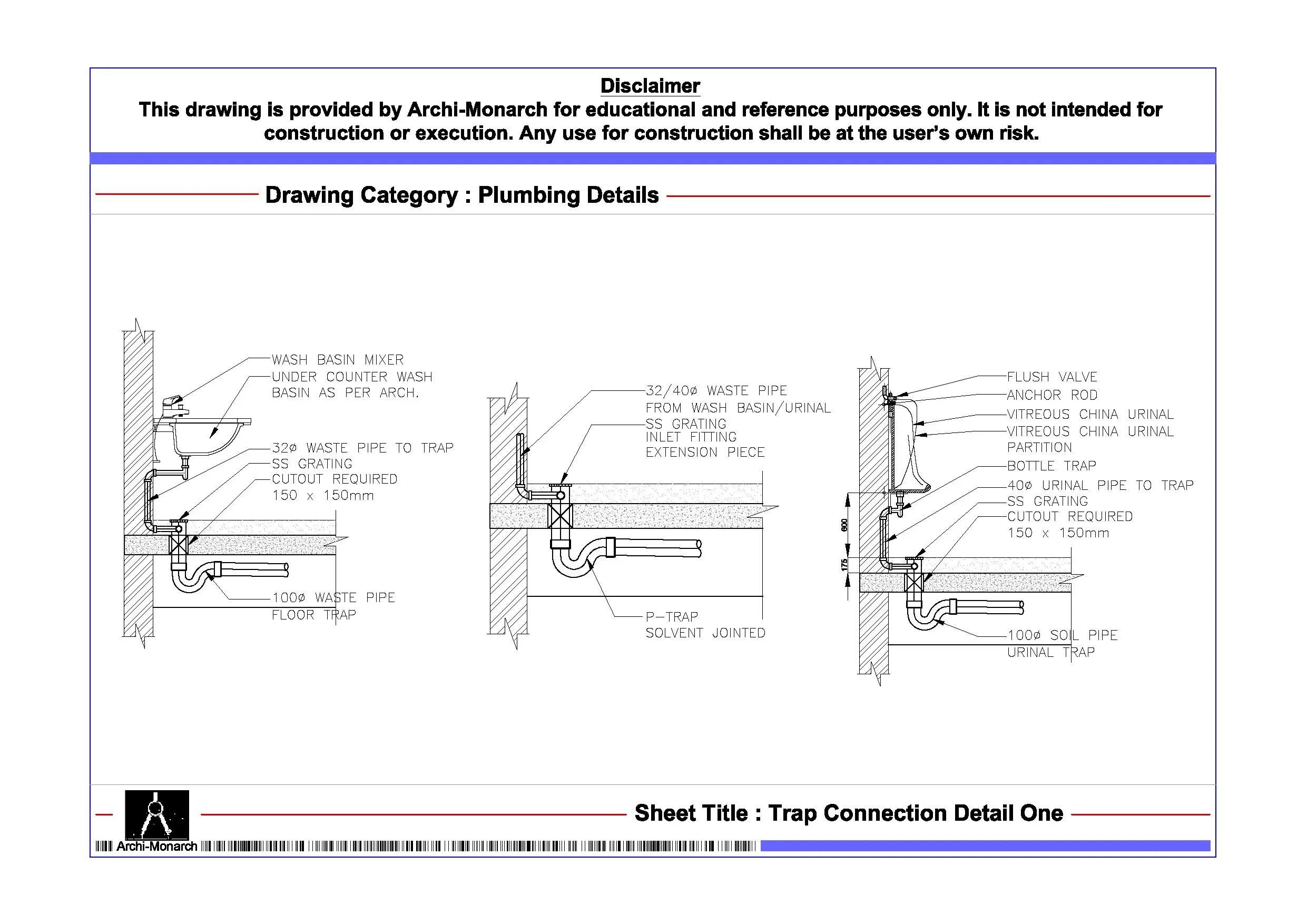
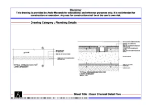
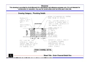
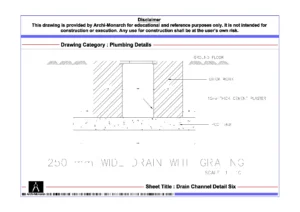
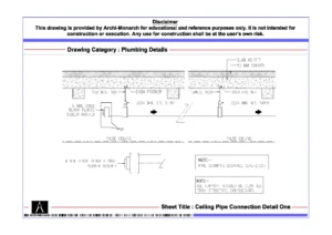
This CAD package clearly presents grease trap and inspection chamber construction through detailed drawings. It includes sectional views, plan layouts, and construction details in a structured format. The drawings show chamber dimensions, pipe connections, and layout alignment. They also illustrate placement in kitchens, service areas, and external drainage zones.
Key components such as grease trap chambers, baffle walls, inlet and outlet pipes, inspection chambers, covers, and frames are clearly defined. The drawings also explain flow direction, sediment collection, and access points. These features support efficient operation and easy maintenance.
The set also covers structural aspects such as RCC construction, waterproofing, and sealing. These details help prevent leakage and contamination. As a result, users gain practical insight into designing reliable and hygienic drainage systems.
The drawings follow professional architectural drafting standards. They use accurate dimensions, clear line hierarchy, and organized annotations. This makes them easy to read and understand. Students can apply similar detailing techniques in academic projects and CAD exercises.
Users can edit the files to modify chamber sizes, adjust pipe layouts, or refine details. This flexibility allows adaptation to different site conditions and project needs.
The DWG format ensures compatibility with AutoCAD and other CAD software. Users can easily integrate these drawings into workflows, presentations, and documentation. The set also supports coordination between plumbing, civil, and service layouts, improving overall drafting accuracy.
Key Highlights:
- GT and IC detail drawing in DWG format
- Intended for educational and reference use
- Includes sectional and plan details
- Shows grease trap chambers, inspection chambers, and pipe connections
- Covers flow control, maintenance access, and structural details
- Follows professional architectural drafting standards
- Fully editable and AutoCAD-compatible files
- Suitable for architecture students and drafting learners
This drawing set is not a construction-ready document. Always consult qualified plumbing engineers and follow local drainage standards before using it in real projects.


Reviews
There are no reviews yet.