
Description
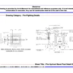
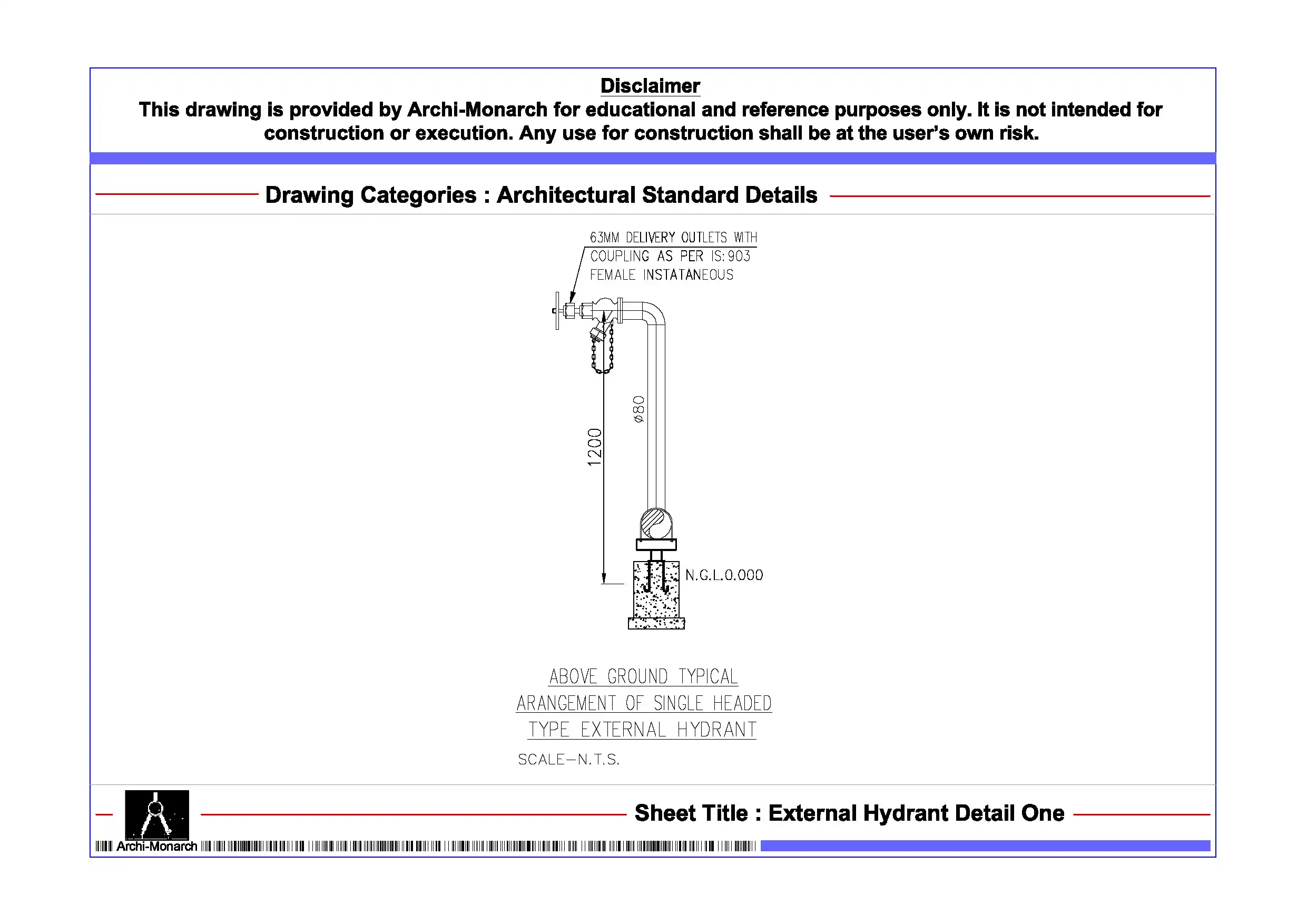
The Fire Hydrant Stand Post Detail presents a professionally prepared architectural fire fighting drawing set in DWG format. It serves educational and reference purposes. Fire hydrant stand posts play a key role in external fire protection systems. They provide direct water access during emergencies. Designers commonly place them in open areas and along building perimeters. Therefore, architecture students and drafting professionals must understand hydrant stand post detailing.
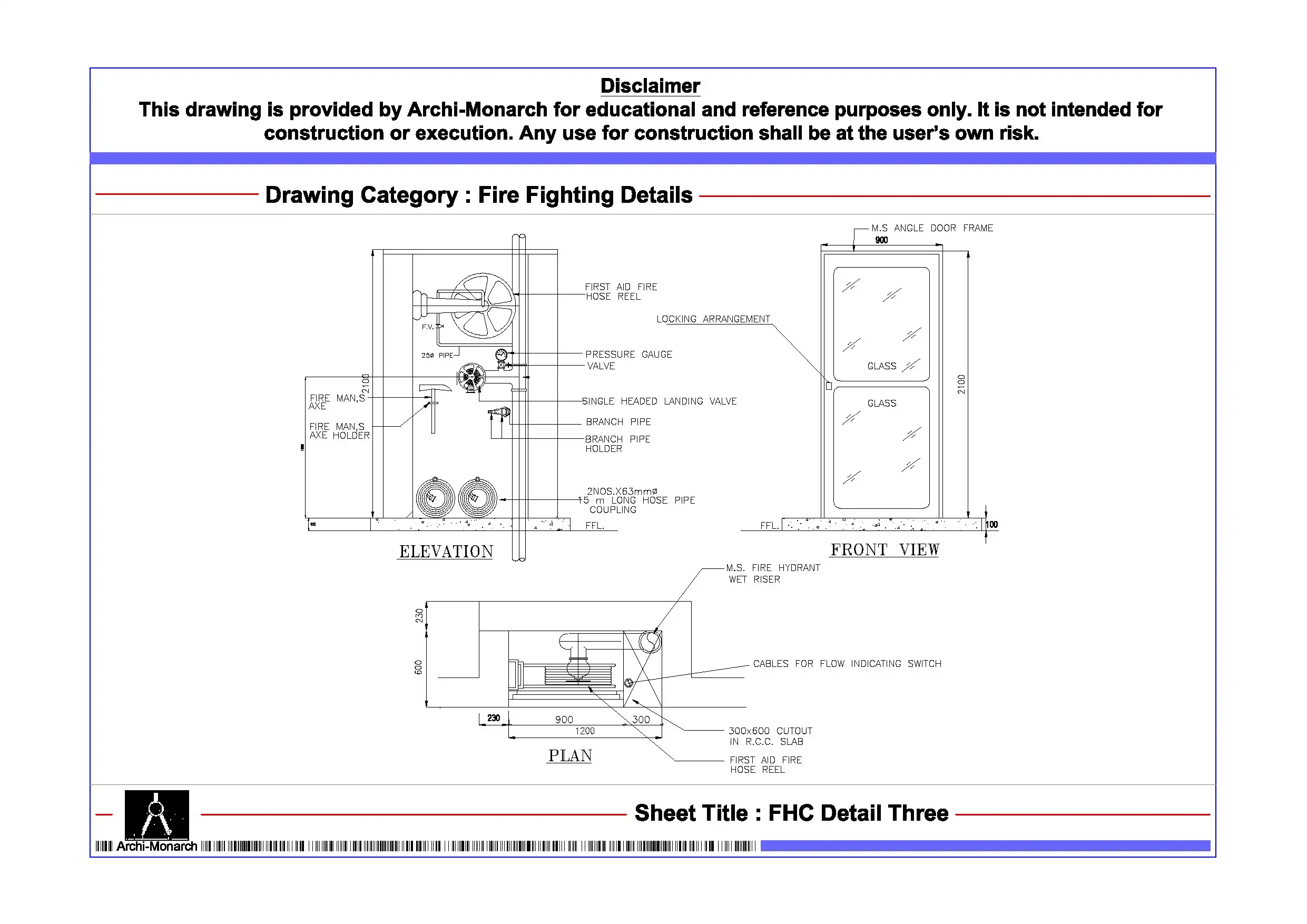
This CAD package clearly explains fire hydrant stand post installation through detailed drawings. It includes plan layouts, sectional views, elevations, and construction details. The drawings follow a clear and structured format. In addition, the set explains stand post positioning and shows pipe connections to underground fire lines. It also demonstrates integration with hydrant systems. The drawings highlight valve arrangements, outlet connections, and protective enclosures. They also define accessibility requirements. As a result, users gain practical knowledge of hydrant stand post design and functionality.
Moreover, the drawings follow professional architectural and fire fighting drafting standards. They use accurate dimensions and maintain a clear line hierarchy. The annotations remain well organized for easy understanding. Therefore, students can read and apply these details in academic projects. Users can edit the files easily, which allows them to modify layouts and refine designs.
The DWG format ensures compatibility with AutoCAD and other CAD software. Users can directly integrate these drawings into project workflows and presentations. In addition, the drawing set improves coordination between architectural layouts, site planning, and fire fighting systems. This approach enhances overall design clarity and technical accuracy.
Key Highlights:
- Architectural fire hydrant stand post detail in DWG format
- Suitable for educational and reference use only
- Includes plan, section, elevation, and construction details
- Shows stand post positioning and pipe connections
- Covers valve arrangements and outlet connections
- Includes protection and accessibility considerations
- Follows professional drafting standards
- Fully editable and AutoCAD-compatible files
This drawing does not serve as a construction-ready document. Always consult qualified fire protection engineers and professionals before using it in real projects.


Reviews
There are no reviews yet.