

Description
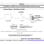
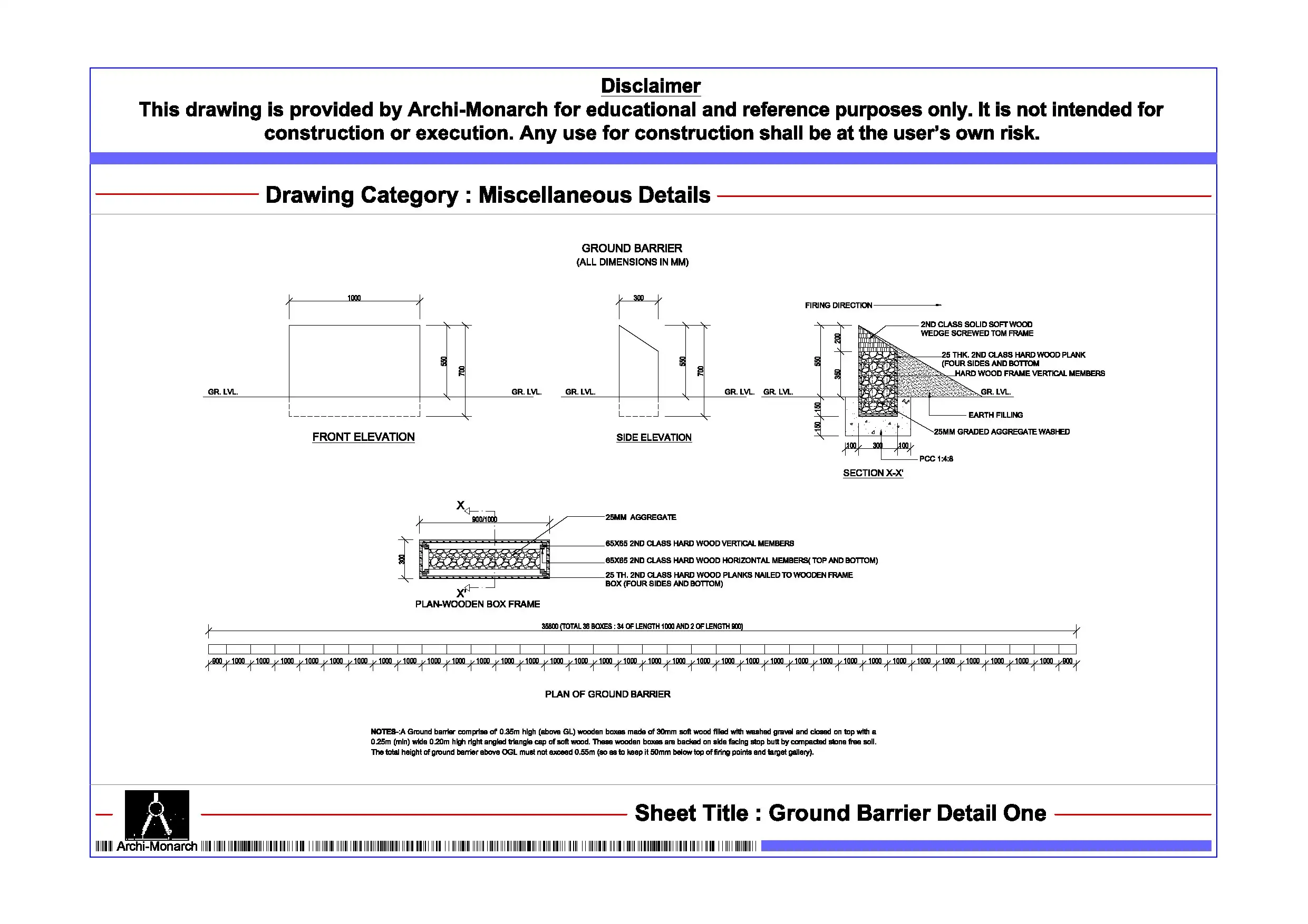
The Ground Barrier Detail is a professionally prepared architectural miscellaneous drawing in DWG format. It serves educational and reference purposes. Ground barrier systems play an important role in protecting buildings from moisture, soil movement, and environmental impact. Therefore, they act as a separation layer between the structure and ground conditions. As a result, they improve durability, stability, and long-term performance of the building.
This DWG file provides a detailed ground barrier construction system. In addition, it suits residential buildings, commercial projects, basements, podium structures, industrial sites, and infrastructure developments. The drawing includes barrier layers, waterproof membranes, protective coatings, insulation layers, sub-base preparation, and structural interfaces. Furthermore, it allows users to study installation methods and construction sequencing. Moreover, it helps define performance aspects such as moisture resistance, soil protection, load distribution, and structural safety. Consequently, users can design efficient and durable foundation protection systems.
Moreover, the drawing follows professional architectural and structural standards. It maintains proper scale, clear annotations, and organized layers. As a result, it ensures clarity and smooth workflow. Therefore, students can easily understand ground barrier systems and foundation protection principles. Similarly, professionals can use it as a reference for working drawings and execution details. The file remains fully editable, so users can customize it as required. In addition, they can adapt it to suit different soil conditions, waterproofing systems, and project requirements.
The DWG format ensures compatibility with AutoCAD and similar drafting software. Thus, users can open, edit, and integrate the drawing easily. This also helps save time during design development. Furthermore, it supports coordination with architectural, structural, and landscape drawings.
This ground barrier detail suits various project types. For example, designers use it in basements, podiums, foundations, retaining structures, and site development works. Overall, it supports both academic learning and professional workflows.
Key Highlights:
- Ground barrier detail drawing in DWG format
- Intended for educational and reference use only
- Includes barrier layers, waterproofing, and protection systems
- Suitable for foundation and substructure design
- Helps define moisture protection and structural safety
- Fully editable and easy to customize
- Compatible with AutoCAD and similar software
- Suitable for students and professionals
This drawing is not a construction-ready document. Therefore, always consult qualified professionals before using it in real projects.


Reviews
There are no reviews yet.