

Description
The Sluice Valve Chamber Detail is a professionally prepared architectural plumbing drawing set provided in DWG format for educational and reference purposes. Sluice valve chambers are critical components in water supply and distribution systems, as they house valves used to control, regulate, or isolate the flow of water within pipelines. Therefore, understanding sluice valve chamber detailing is essential for architecture students and drafting professionals involved in plumbing and infrastructure design.
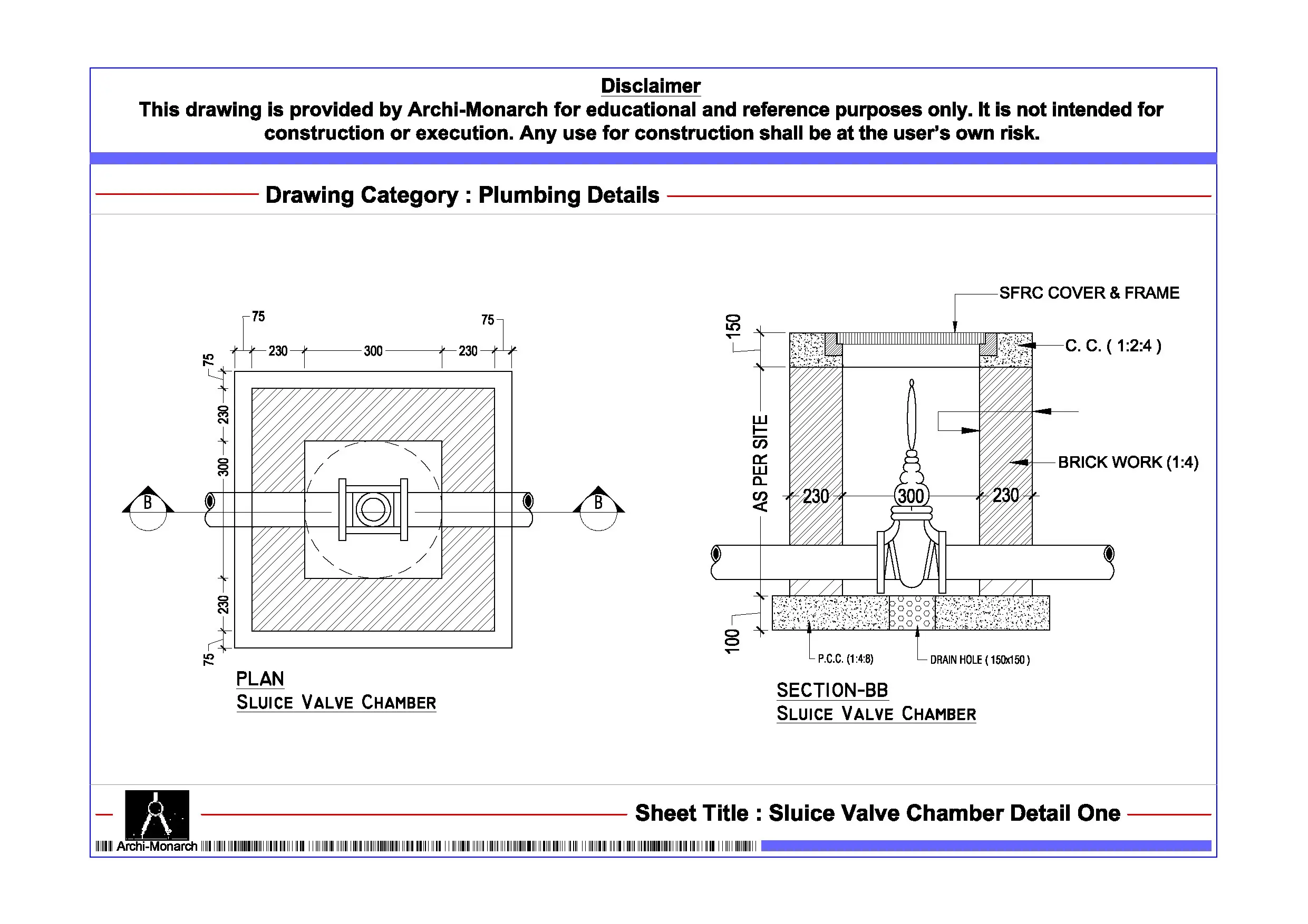
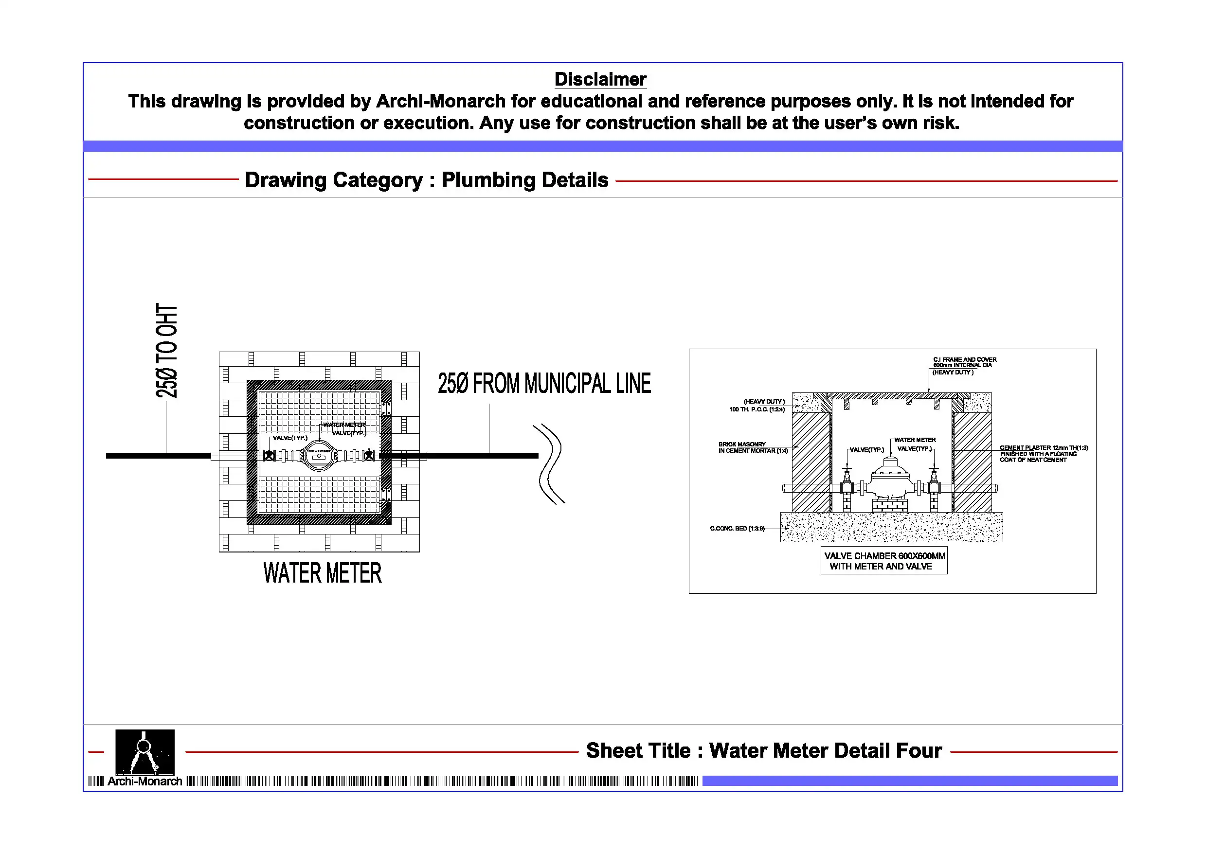
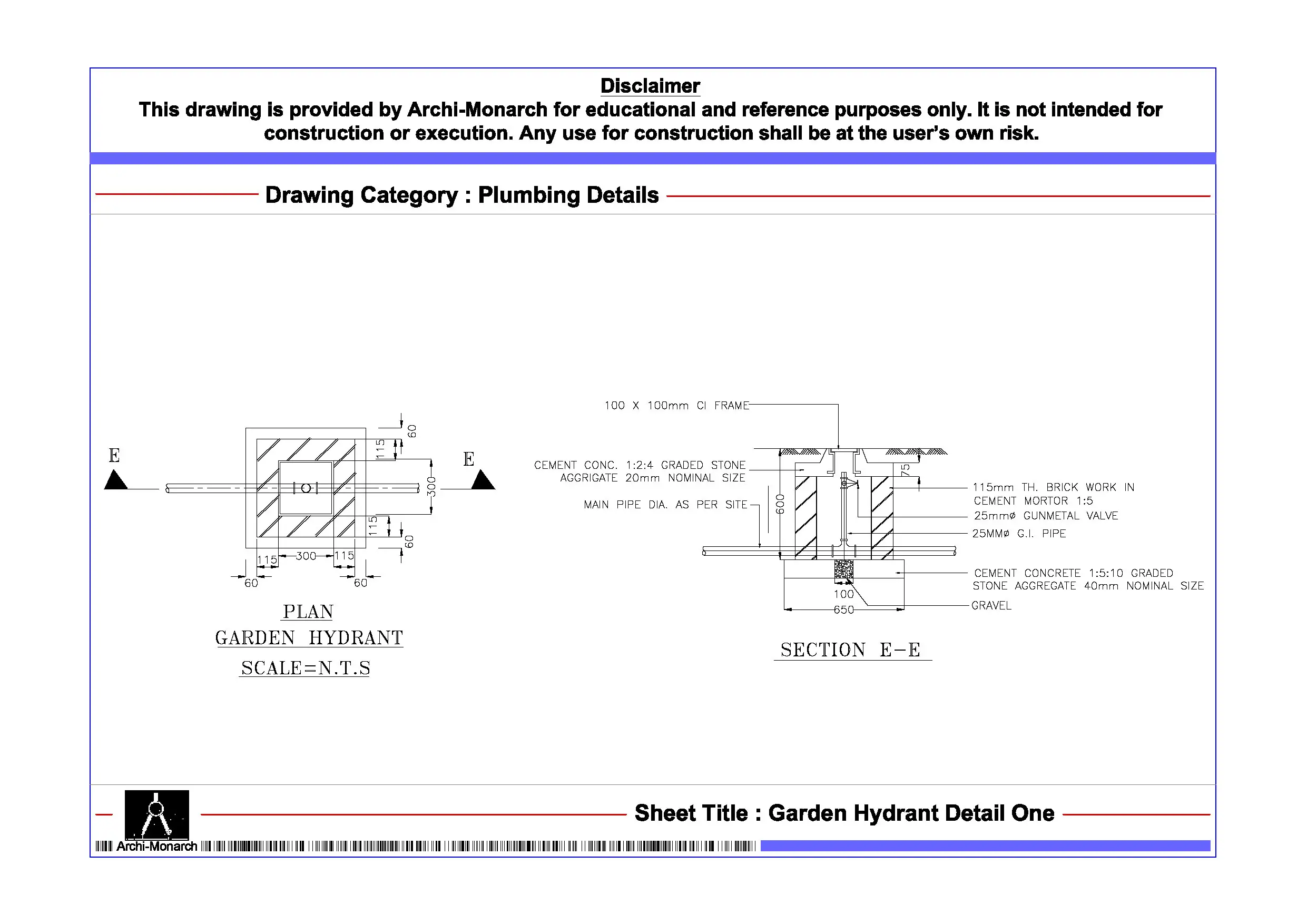
This architectural CAD package clearly illustrates sluice valve chamber construction through detailed drawings. It includes plan layouts, sectional views, and key construction details presented in a structured and coordinated format. In addition, the drawing set explains chamber dimensions, depth, and internal layout required to accommodate valve installation and operation. It also highlights inlet and outlet pipe connections, valve positioning, support arrangements, and access provisions such as covers and ladders or step irons. As a result, learners gain practical insight into how valve chambers are designed to ensure operational efficiency, maintenance accessibility, and system reliability.
Moreover, the drawings follow professional architectural and plumbing drafting standards. They use accurate dimensions, clear line hierarchy, and well-organized annotations. Consequently, students can interpret the drawings easily and apply similar detailing techniques in academic projects and CAD exercises. Since the files remain fully editable, users can modify chamber sizes, adjust valve positions, or refine detailing to explore different water supply system configurations.
The DWG format ensures seamless compatibility with AutoCAD and other commonly used CAD software. Therefore, users can directly integrate these drawings into project workflows, presentations, and documentation sets without additional conversion. In addition, the drawing set supports coordination between architectural layouts, civil infrastructure, and plumbing systems, which improves overall drafting clarity and technical accuracy.
Key Highlights:
- Architectural sluice valve chamber detail drawing in DWG format
- Intended strictly for educational and reference use
- Includes plan, section, and construction detailing
- Shows valve positioning, pipe connections, and chamber layout
- Covers access provisions and maintenance considerations
- Prepared using professional architectural and plumbing drafting standards
- Fully editable and AutoCAD-compatible CAD files
- Suitable for architecture students and drafting learners
This drawing set does not represent a construction-ready document. Always consult qualified architects, civil engineers, and plumbing professionals before applying any detail in real projects.


Reviews
There are no reviews yet.