


Description
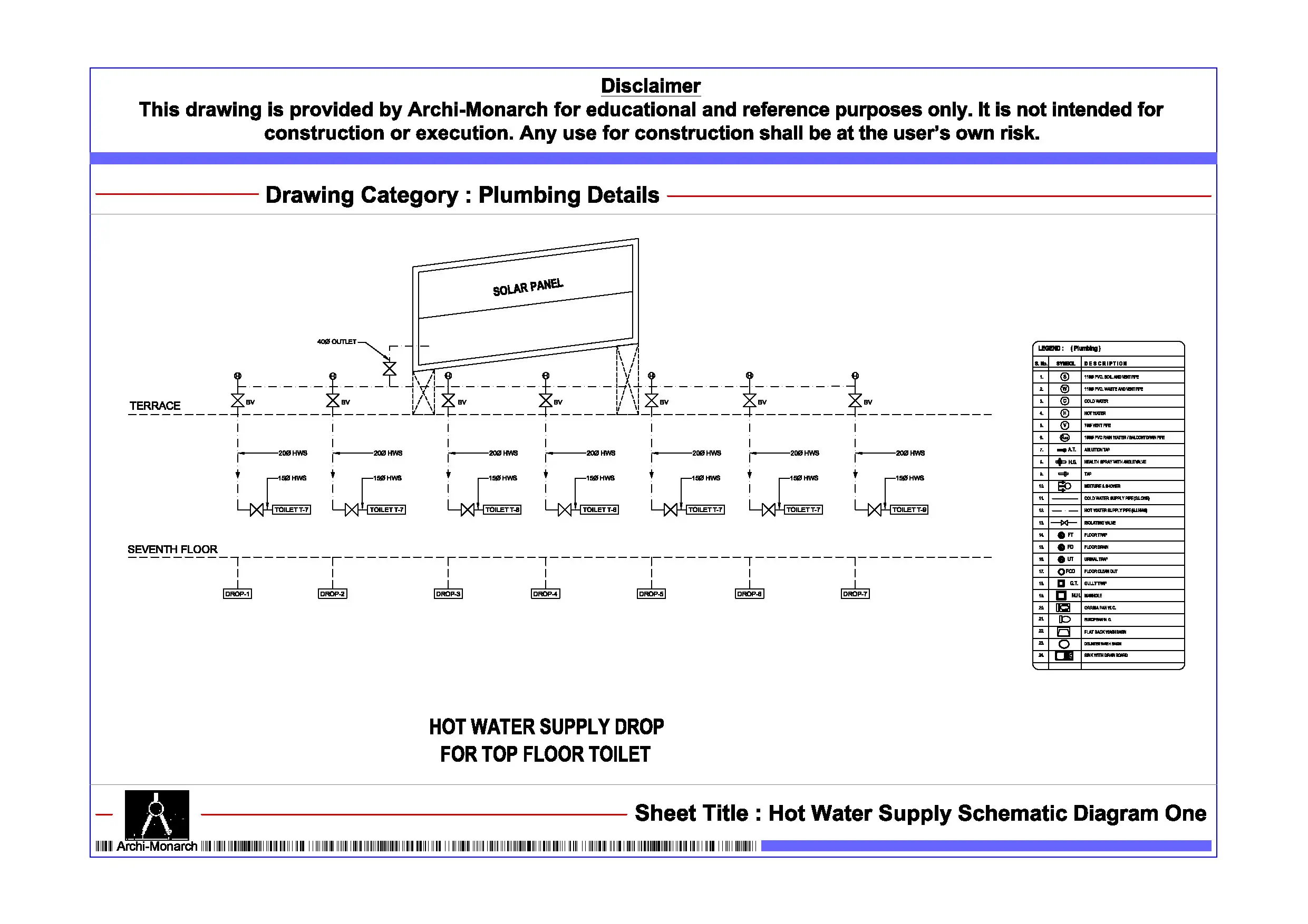
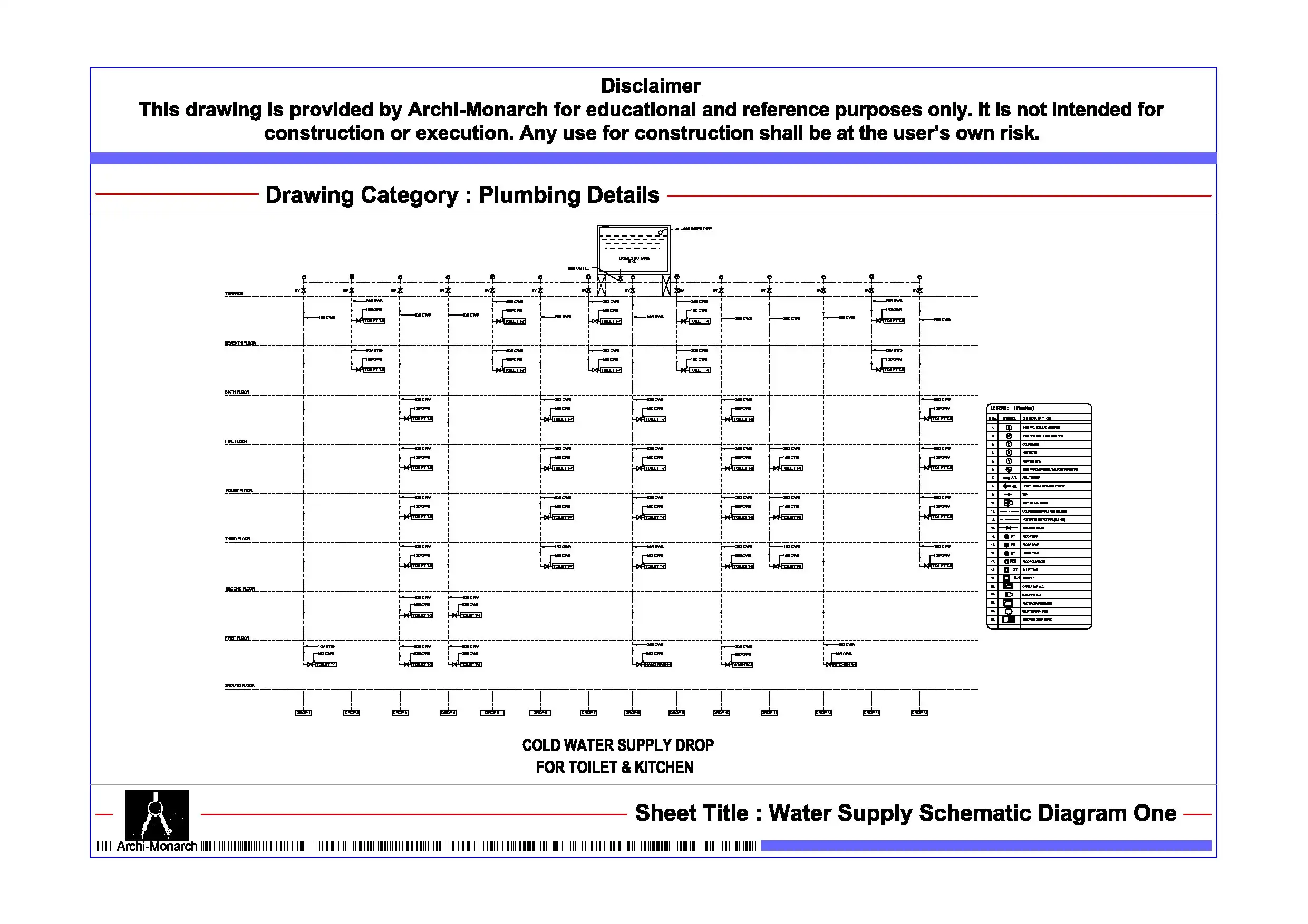
The Hot Water Supply Schematic Diagram provides a professionally prepared architectural plumbing drawing set in DWG format for educational and reference purposes. Hot water supply systems are essential in residential, commercial, and institutional buildings, ensuring user comfort and hygiene. Designers must carefully plan these systems to achieve efficient water distribution, maintain temperature consistency, and reduce energy loss. Therefore, architecture students and drafting professionals must understand hot water system schematics to design efficient and well-coordinated plumbing networks.
This architectural CAD package clearly presents hot water supply systems through schematic diagrams. It includes diagrammatic representations and technical layouts in a structured and easy-to-understand format. The drawing set explains the flow of hot water from the source to various fixtures within the building. It also highlights key components such as water heaters (instant or storage), distribution pipes, circulation lines, valves, pumps, and fixtures like basins, showers, and sinks.
In addition, it covers system configurations, pipe routing strategies, and connection methods that ensure efficient operation and minimal heat loss. The drawings also address insulation, pressure control, and return circulation systems to maintain consistent temperature and improve performance. As a result, users gain practical insight into designing hot water systems that enhance efficiency, reduce energy consumption, and provide reliable service.
Moreover, the drawings follow professional architectural and drafting standards. They use clear symbols, logical flow diagrams, and well-organized annotations. Consequently, students can easily interpret the schematics and apply similar principles in academic projects and CAD exercises. Users can edit the files freely to modify system layouts, adjust pipe routing, or refine detailing to suit different building types and plumbing requirements.
The DWG format ensures seamless compatibility with AutoCAD and other commonly used CAD software. Therefore, users can directly integrate these drawings into project workflows, presentations, and documentation sets without additional conversion. In addition, the drawing set supports coordination between plumbing systems, mechanical equipment, and building services, which improves drafting clarity and technical accuracy.
Key Highlights:
- Hot water supply schematic diagram in DWG format
- Intended strictly for educational and reference use
- Includes schematic layouts and system diagrams
- Shows heaters, distribution pipes, valves, and circulation systems
- Covers pipe routing, insulation, and temperature control strategies
- Prepared using professional architectural and drafting standards
- Fully editable and AutoCAD-compatible CAD files
- Suitable for architecture students and drafting learners
This drawing set does not serve as a construction-ready document. Always consult qualified plumbing and mechanical engineers before applying any detail in real projects.


Reviews
There are no reviews yet.