
Description
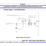
The Zonal Control Valve Detail presents a professionally prepared architectural fire fighting drawing set in DWG format. It serves educational and reference purposes. Zonal control valves play a vital role in fire protection systems, as they regulate water flow within specific zones. In addition, they help isolate sections during maintenance or emergencies. Therefore, architecture students and drafting professionals must understand zonal control valve detailing.
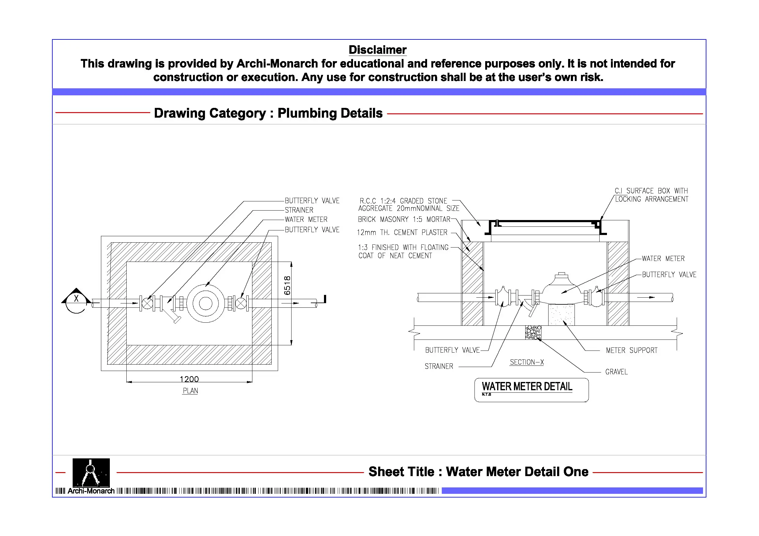
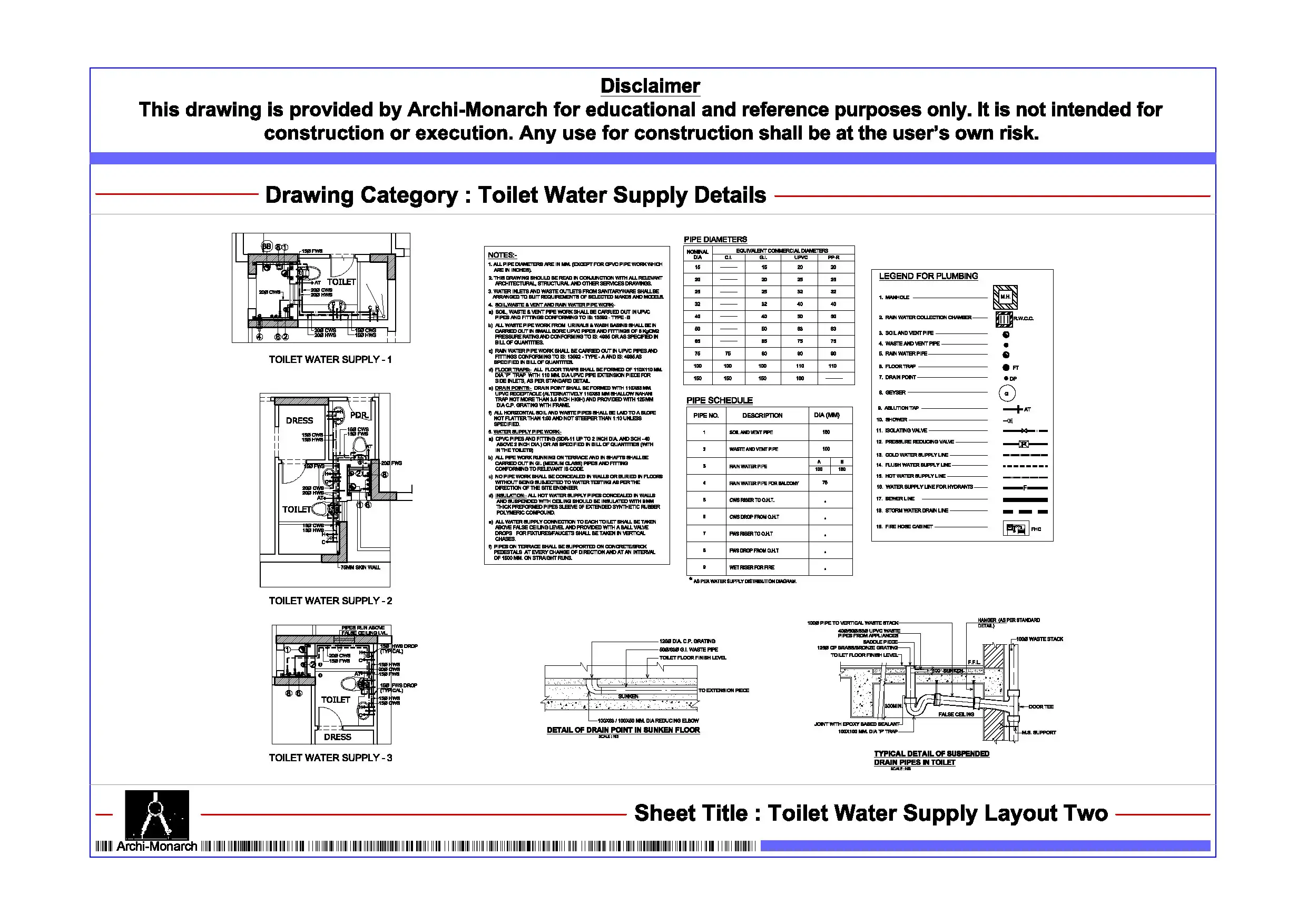
This CAD package clearly explains zonal control valve installation through detailed drawings. It includes plan layouts, sectional views, elevations, and construction details. Each drawing follows a clear and structured format. In addition, the set shows valve positioning within fire sprinkler or hydrant networks. It also explains pipe connections and control arrangements. Furthermore, the drawings highlight pressure gauges, flow switches, and drain connections. As a result, users can understand how designers manage system control, monitoring, and safety.
Moreover, the drawings follow professional architectural and fire fighting drafting standards. They use accurate dimensions and maintain a clear line hierarchy. In addition, the annotations remain well organized and easy to read. Therefore, students can easily interpret and apply these details in academic projects. Similarly, users can edit the files without difficulty, which allows them to modify layouts and test different system configurations.
The DWG format ensures full compatibility with AutoCAD and similar CAD software. Therefore, users can directly integrate these drawings into project workflows and presentations. In addition, the drawing set improves coordination between fire protection systems, architectural layouts, and service networks. As a result, this approach enhances overall design clarity and technical accuracy.
Key Highlights:
- Architectural zonal control valve detail in DWG format
- Suitable for educational and reference use only
- Includes plan, section, elevation, and construction details
- Shows valve positioning and pipe connections
- Covers gauges, flow switches, and drain arrangements
- Helps control and isolate fire protection zones
- Follows professional drafting standards
- Fully editable and AutoCAD-compatible files
This drawing does not serve as a construction-ready document. Therefore, always consult qualified fire protection engineers and professionals before using it in real projects.


Reviews
There are no reviews yet.