


Description
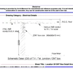
The Location Of ONT Box Detail presents a professionally prepared architectural electrical drawing set in DWG format. It supports educational and reference use only. An ONT (Optical Network Terminal) box plays a key role in modern communication systems. It connects fiber optic networks to internal building services. Therefore, architecture students and drafting professionals must understand proper ONT box placement and coordination.
This architectural CAD package clearly explains ONT box location and installation requirements. It includes plan layouts, sections, elevations, and construction details. Moreover, each drawing follows a clean and structured format. In addition, the set shows ONT box positioning within residential and commercial spaces. It also explains cable routing, conduit paths, and access requirements. As a result, learners understand how telecom systems integrate with building design.
The drawings highlight fiber cable entry points and internal routing paths. Furthermore, they show how the ONT box connects with electrical panels and communication systems. In addition, the set explains mounting height, clearance, and accessibility considerations. Therefore, users gain a clear understanding of telecom coordination and service planning. Consequently, they can apply these concepts in academic and practical projects.
The drawings follow professional architectural and electrical drafting standards. For example, they use clear line weights, accurate dimensions, and proper annotations. In the same way, the drawings maintain clarity and consistency. As a result, students can easily read and interpret the details. Moreover, they can apply similar methods in their CAD workflows.
Users can fully edit the files. For instance, they can adjust ONT box locations, modify routing paths, or refine installation details. In addition, the DWG format works smoothly with AutoCAD and similar software. Therefore, users can directly use these drawings in presentations and documentation. Furthermore, the set supports coordination between architectural, electrical, and communication systems.
Key Highlights:
- Architectural ONT box location detail in DWG format
- Supports educational and reference use only
- Includes plan, section, elevation, and construction details
- Shows ONT box placement, cable routing, and conduit layout
- Covers mounting height, accessibility, and service coordination
- Follows professional architectural and electrical drafting standards
- Provides fully editable and AutoCAD-compatible files
- Suitable for students and drafting professionals
This drawing set does not serve as a construction document. Therefore, always consult qualified electrical and telecom professionals before execution.


Reviews
There are no reviews yet.