

Description
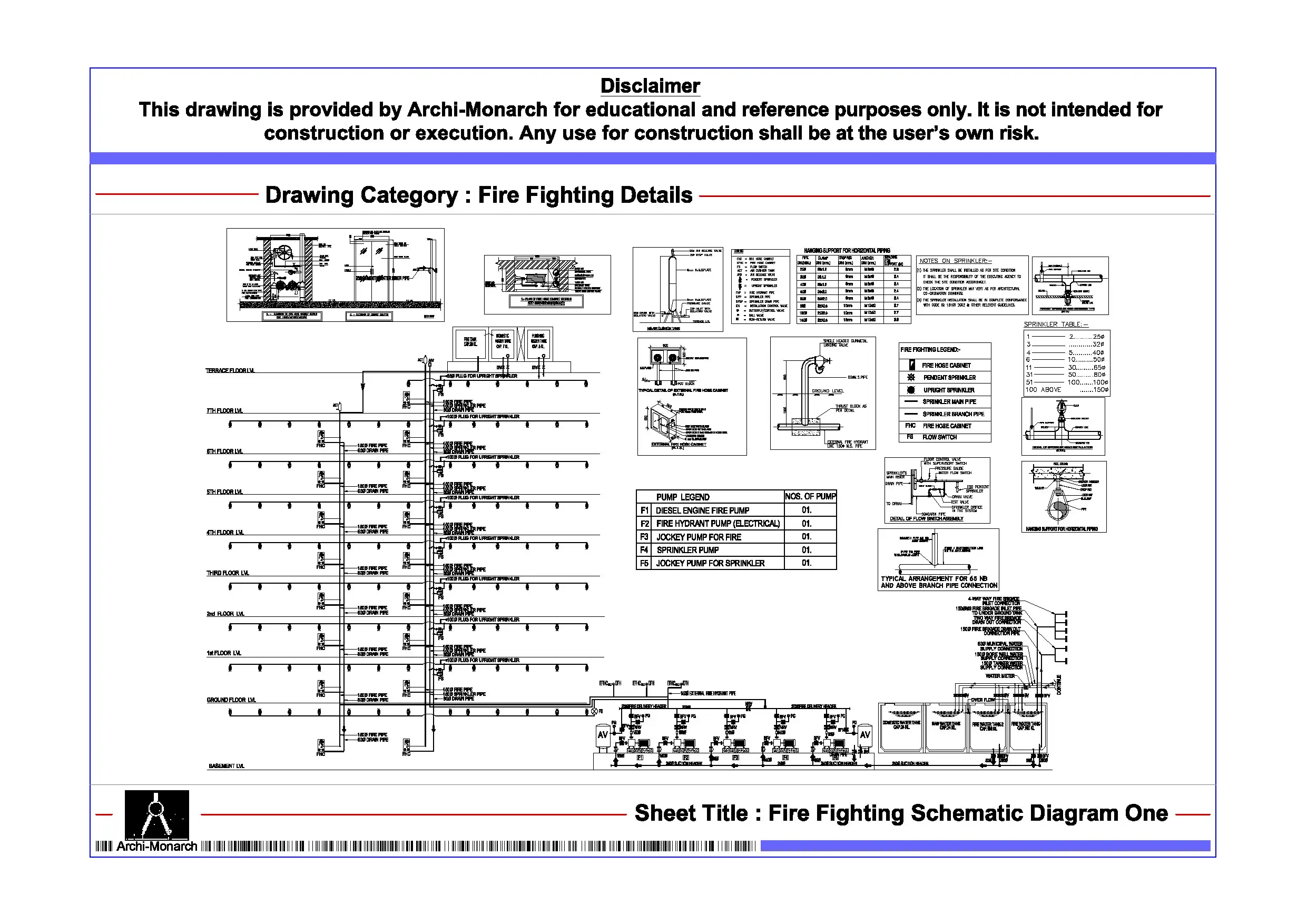
The Fire Fighting Schematic Diagram is a professionally prepared architectural fire fighting drawing set in DWG format. It is intended for educational and reference purposes. Fire fighting schematics help explain how systems operate inside a building. They show how water flows from the source to different firefighting components. Therefore, learning schematic representation is essential for architecture students and drafting professionals working in fire safety and building services.
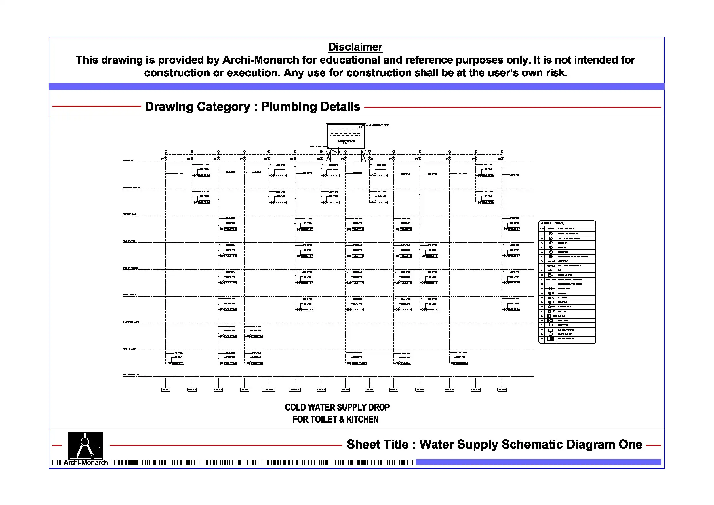
This CAD package presents the fire fighting system in a simplified format. It converts complex piping networks into clear and easy diagrams. The drawing includes system layouts showing connections between fire water tanks, fire pumps, and distribution lines. It also covers hydrant systems and sprinkler networks. In addition, the drawings explain pipe routing and connection hierarchy. Key components such as valves, alarms, and control systems are clearly marked.
The schematic also highlights vertical risers and horizontal pipelines. It shows terminal points like hydrants and sprinkler heads. As a result, users can understand how water distribution works during emergencies. This improves clarity in system planning and design understanding.
Moreover, the drawings follow professional fire fighting drafting standards. They use clear symbols, proper line weights, and simple annotations. Therefore, students can read and understand them easily. They can also apply these methods in academic and CAD projects. Since the files are fully editable, users can modify layouts and adjust system components.
The DWG format ensures easy use in AutoCAD and other CAD software. Users can directly include these drawings in their projects and presentations. In addition, the drawings support coordination between architecture, structure, and fire protection systems. This improves overall design accuracy and workflow efficiency.
Key Highlights:
- Architectural fire fighting schematic diagram in DWG format
- For educational and reference use only
- Shows complete fire protection system layout
- Includes tanks, pumps, valves, hydrants, and sprinklers
- Covers vertical risers and horizontal distribution lines
- Prepared using professional drafting standards
- Fully editable and AutoCAD-compatible files
- Ideal for students and drafting professionals
This drawing is not a construction-ready document. Always consult qualified fire protection engineers and professionals before using it in real projects.


Reviews
There are no reviews yet.